The damping and vibration reduction design of electronic equipment is based on the working environment conditions of the instrument and equipment, some special requirements of itself and the possibility and reality of implementing these requirements. By making use of the relationship between the parameters of damping structure and each other, the main parameters are adjusted properly. The damping and damping design can be roughly summarized as follows:
1. Determine the type of structural damping and the damping form of the whole machine.
2. Determine the elastic element material of the damping structure.
3. Determine the viscoelastic damping material.
4. The dynamic characteristics of damping structure are estimated and measured.
The practical test and engineering design practice make us realize that it is not necessary and impossible for modern electronic control equipment to design the structural damping of the whole system, but flexible measures should be taken according to the specific situation. Generally, the damping design of hierarchical structure is adopted. This is mainly based on the characteristics of some modern electronic control equipment, such as small size, light weight, good air tightness, high reliability, complex and variable shape, etc. I. the processing and molding technology and economy should be considered. The so-called hierarchical structure damping design processing, that is to say, the whole instrument is composed of several damping structural components. Thus, the vibration response of each important part of electronic equipment is limited within the allowable range.
It should be specially pointed out that the harmonic frequencies of the main parts of the designed equipment must be staggered to avoid the coupling between them.
A. The first stage damping system of the base plate of the rectangular damping structure
The design features of the damping system are: simple, economic, easy to operate, and has good damping effect. It is suitable for the design of electronic control instruments with moderate protection requirements for broadband random vibration. The concrete method is: on a multi-layer damping structure base plate composed of three layers of viscoelastic damping material and four layers of aluminum alloy Mei. Install a cast aluminum structure instrument shell, and the important components such as printed circuit board in the shell are not subject to structural damping treatment, as shown in the figure:
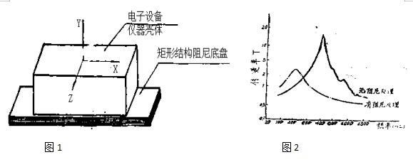
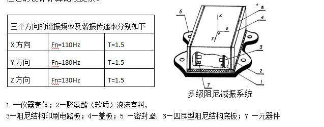
In such a simple damping system, the typical transfer rate curve of the instrument in the direction perpendicular to the base plate (Ya direction) according to the coordinates shown in Figure 1 is shown in Figure 2. Figure 2 shows the vibration acceleration response of the instrument in two states before and after the installation of damping base plate. In the test, we measure the vibration response at the center of the top surface of the instrument, and the excitation acceleration is subject to the vibration table. The first resonance frequency of the top surface of the undamped bottom plate is 600Hz, and the resonance transmission rate is 13; the second resonance transmission rate of the second mode at 1300hz is 4.6. If a damping base plate is added to the bottom of the instrument, the resonance transmission rate will be significantly reduced, and it has good vibration isolation performance under high excitation frequency. The resonance frequency in the direction perpendicular to the base plate (Y direction) is 75Hz, and the resonance transmission rate is 2.8. Due to the damping structure of the bottom plate, a considerable part of the vibration energy can be dissipated through it, so the resonance transmission rate of the basic vibration mode of the instrument with damping base plate can be reduced by 4? 5 times compared with that without damping base plate. In addition, the damping base plate reduces the resonance frequency of the instrument system, so it has a good isolation effect on the excitation frequency greater than 110hz. The vibration damping effect of the instrument in X and Z directions is also ideal. The resonance frequency in X direction is 70Hz, and the resonance transmission rate is 2.3; the resonance frequency in Z direction is 32Hz, and the resonance transmission rate is 1.3.
In addition to the above characteristics, the instrument system with damping structure base plate for primary damping and vibration reduction can easily maintain the independent sealed shell structure of the instrument, provide a good working environment for the instrument, and further improve the working reliability of the instrument.
Up to now, some electronic instruments still use rubber damper to isolate vibration. This method not only needs a large number of shock absorbers, but also requires a large increase in the volume and structure weight of the instrument due to the installation of the shock absorbers; and the use of the shock absorbers also needs enough space to avoid mutual collision due to the excessive low frequency harmonic amplitude value; moreover, the effect of resonance control is poor. However, the instrument system with damping structure base plate for primary damping can completely overcome the shortcomings in the vibration isolation system. In particular, the volume and weight of the instrument can be reduced by nearly one-third compared with that of the vibration isolation design with shock absorbers.
See Table 1 for the damping composition and vibration test data of the base plate of the rectangular damping structure. They are made of aluminum alloy plate (four layers) as elastic layer and a thick sandwich multilayer damping structure composed of zn8 damping materials (three layers). They are mostly used in the design of damping system of modern electronic control equipment
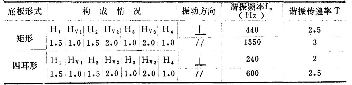
Multi stage damping vibration isolation system for B, four ear type damping structure bottom plate and (soft) foam plastic
Modern electronic control equipment is usually composed of many resistors, capacitors, transistors, relays and various components. If some of these components (such as relays or some components) are sensitive to vibration, impact and other mechanical environment conditions, if the simple damping design method described above is still used, it will obviously not meet the requirements. Therefore, multi-stage damping design should be considered. The main feature of this damping system is that it can limit the maximum vibration transmission rate to about 2, and improve the working environment of the instrument to the greatest extent, but its design and calculation are complex.
The resonance frequency and resonance transfer rate in three directions are as follows
The specific implementation of the multi-stage damping system is to install a welded integral aluminum alloy structure shell on a multi-layer four ear damping base plate composed of four layers of aluminum alloy plates and three layers of damping materials. Inside it, the printed circuit boards and battery mounting plates of the components are also made into asymmetric and symmetrical thick damping sandwich structures, and the damping of polyurethane foam is used as an auxiliary measure. Therefore, the electronic control equipment not only meets the requirements of working environment of components, but also ensures the special requirements of the instrument itself, achieves the purpose of damping and vibration reduction, achieves the ideal effect, and meets the requirements of engineering design. According to the direction shown in the figure above, the mechanical environment tests such as vibration and impact are carried out for the electronic instrument. The results show that the instrument works normally and the electrical performance parameters fully meet the design requirements. The structure of the base plate of the four ear damping structure is the same as that of the rectangular damping structure, and the vibration test data are shown in the table.
See the figure below for the damping treatment form of printed circuit board for electronic equipment. The specific method is to paste a certain thickness of zn8 damping material on the non printed circuit surface of the ordinary printed circuit board (as the base), and then paste a structural board with the same material as the base as the constraint layer, whose thickness can be the same as or different from the base, that is, symmetrical or asymmetrical. By comparing the vibration data of PCB before and after damping treatment, it can be clearly seen that the resonance frequency is reduced from 400Hz to 220hz, and the resonance transmission rate is reduced from 18 to 3.2. PCB is located in the actual installation position of the instrument with damping base plate, which provides an ideal working environment for electronic components and improves the damping effect of electronic equipment system. The typical vibration transmission rate curve is shown in the figure.
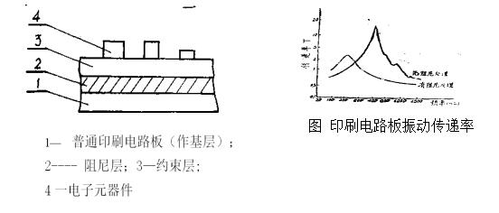
There are two types of PCB structure for electronic equipment: symmetrical type and asymmetric type. They are mainly different damping measures according to the specific situation and needs of engineering design. For example, in the equipment shown in the figure, the battery mounting plate is of symmetrical damping structure, while the printed circuit board installed with electronic components, due to the limitation of the internal space of the equipment, should adopt asymmetric damping structure. In this way, the total thickness of the battery mounting plate can be reduced after damping treatment, which adapts to the specific situation of narrow internal space. It has been proved that the loss factor of asymmetric damping structure is almost the same as that of symmetric damping structure, that is to say, there is no significant difference in vibration transmission rate between them. Using this feature skillfully can bring us great convenience in our design work sometimes.
C. Integrated application system of structural damping and USS reduction
The comprehensive application of viscoelastic shear damping and shock absorber is also one of the effective methods to control vibration. It can also make modern electronic equipment have the ability of highly controlling vibration and impact in the whole frequency range of excitation frequency, and provide a better working environment for electronic equipment. Here is an example:
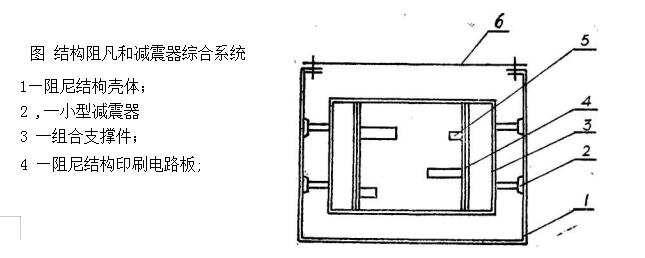
1. Local damping treatment and comprehensive application of shock absorber
There are often such cases, some modern electronic control equipment, their own volume and weight are not large, but they are in a very bad mechanical environment, so effective vibration control measures must be taken. However, the shape and installation of these equipment are very special. If only using structural damping treatment, it is more difficult, and the further reduction of equipment volume and weight has no more effect. However, the small shock absorber system is easy to realize because of its small volume and weight, but its resonance control ability is poor. Therefore, the vibration control of the composite structure with shock absorber and local structure damping is adopted. The typical system for the comprehensive application of the local structure damping of the shock absorber is shown in the figure below. It uses the instrument shell as the shock absorber support and adopts the structural damping treatment, so that the vibration excitation degree of the isolated part of K57 is different, and the vibration environment is relatively improved. Several damping structure printed circuit boards are hung in the vibration isolation system composed of four small rubber shock absorbers through the combination of supports (both stiffness and mass are not large), which provides a good high frequency vibration isolation ability of resonance control system for electronic equipment, It reduces the multi peak resonance response, improves the working environment and meets the needs of engineering design.
2. Integrated application system of damper and shock absorber
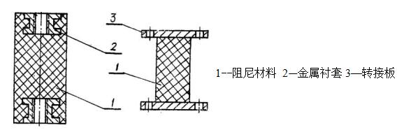
The method of using the system composed of damper and shock absorber to control the vibration is still in the category of vibration isolation, or based on vibration isolation. The difference is that the cylindrical damper made of high damping material is used to dissipate the seismic kinetic energy in low frequency resonance, so as to achieve the purpose of low frequency resonance control. Damper is developed on the basis of free damping treatment and constrained damping treatment. It is to process the high damping material into a certain geometry damping element according to the design requirements, and place it on some special parts during the assembly process of electronic equipment. It can bear very high acceleration load and has the effect of damping. The typical structure is shown in the figure below.
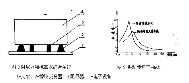
All kinds of layered damping treatments are only suitable for structures and modes with high surface strain. For structures with low surface strain (including non layered ones) and instruments with high surface, the damper will play an important role. Therefore, when installing the damper, the damper should be located at the point where high amplitude response is generated, and the integrated system composed of damper and damper is shown in Figure 8. It is composed of four cylindrical dampers symmetrically installed in a common vibration isolation system composed of four rubber dampers. The resonance frequency is 35Hz and the resonance transmission rate is about 2. See Fig. 9 for the comparison between the vibration of the system and the common vibration isolation system in the direction perpendicular to the top surface of the instrument. It can be seen from the curve in the figure that the resonance frequency cap of the common vibration isolation system is 25Hz, and the resonance transmission rate is 9. It starts to decay at about 35Hz, and the high-frequency vibration isolation performance is good. The resonance frequency of the system is 35Hz, and the resonance transmission rate is 1.8. The attenuation starts from 50Hz, and its high frequency attenuation is almost as good as that of the common vibration isolation system.
4: Precautions for design of vibration isolator of vehicle electronic equipment
Damping is one of the main technical measures for vibration protection of modern electronic control equipment. It is necessary to use damping technology in modern electronic equipment, and its damping effect is remarkable.
In order to obtain the best damping effect, the ideal damping material with a high loss factor of 8 and a proper shear modulus of G should be possessed first. In addition, the optimal damping design must be made. Therefore, it is necessary to adjust some parameters properly to achieve the purpose of all design requirements by pre calculation and analysis, using the relationship between parameters in damping structure design.
When evaluating the design effect of a damping system, although the loss factor of the system and the vibration transmission rate of the system are controlled Capacity is the main index, but it should not be regarded as the only criterion to obtain the maximum damping of composite structure, but should be measured comprehensively. For example, in addition to comprehensive consideration of loss factor gate, shear parameter x, geometric parameter Y and optimal design parameter of structure, environmental temperature and boundary condition should not be ignored. Although the half width temperature at0.7 is required to be as large as possible when choosing damping materials, the temperature range that can effectively dissipate the vibration kinetic energy is still limited. In addition, with the different boundary conditions, the effect of the damping characteristics of the structural system is not the same. Therefore, when dealing with the damping structure design, the optimal temperature range, the optimal frequency range, certain boundary conditions, the highest damping, the appropriate strength, stiffness and weight and other factors must be optimized. Only in this way can the optimal damping effect be achieved.
The test and engineering design practice also proved that the use of PTSMA damping technology and vibration isolation technology, foam plastic damping, various forms of dampers, damping pad and other comprehensive use, under certain conditions can also achieve the desired vibration control effect.
Any new thing is in the continuous development to solve problems and continue to develop, so is the electronic equipment vibration isolator. Only in the process of continuous innovation, in line with the principle of use and safety first, the vibration isolator is constantly innovated to improve its practical performance and safety factor. Constantly create our brilliance in the field of vibration isolators. At the same time, the following points should be paid attention to in the design and application of the vibration isolator. First of all, the vibration isolator requires high precision for the components, so it must be ensured that the normal use of the vibration isolator. At the same time, the technical requirements and installation are also difficult, and the maintenance is relatively complex. Therefore, we must do a good job in the preparatory stage, and play a positive role in promoting the design of the vibration isolator. Due to the complexity and particularity of its work, the requirements are also relatively high. Therefore, it is necessary to strengthen the quality of the components, so as to improve the overall performance and safety of the vibration isolator. Secondly, in the working state of the vibration isolator, the requirements for hydraulic oil are relatively high, especially when air or water is mixed in the oil, it will cause the deterioration of the hydraulic oil, which is also a huge test for the performance stability of the vibration isolator system, and will directly affect the working reliability of the vibration isolator. It is of great significance to improve the use of vibration isolators for electronic equipment and ensure the safe use performance of on-board electronic equipment. At the same time, the working state of the vibration isolator shall be independent, which shall not be confused with other work, so as to ensure the independence of the vibration damping work, ensure the consistent working quality of the vibration isolator, and guarantee the safe use of the on-board electronic equipment. Once again, in the installation and design of the vehicle borne electronic equipment vibration isolator, considering the special role between the vehicle and the frame, we need to use the puzmai large density damping buffer block. The function of the puzmai large density buffer block is to form a buffer between the impact force formed by the electronic equipment vibration isolator and the road surface, which is equivalent to an auxiliary spring, which can reduce the vibration effect of the road surface on the vehicle borne electronic equipment The ride comfort is greatly improved. In the design of the vibration isolator, we should strengthen the quality control. Every component should be qualified to ensure that the overall performance of the vibration isolator can be guaranteed and improved, reduce the accident rate of the vibration isolator, and provide reliable quality assurance for the normal operation of the vibration isolator.